
This post is also available in: Türkçe
- What is UART
- UART Communication Protocol
- How does UART Protocol Work
- UART Protocol Result
- UART Protocol MikroC Library
- RESULT
- Library Files
- References
What is UART?
- We will examine the UART, which is one of the data communication protocols, the “universal asynchronous data communication” protocol. After thorough review, you can use this information to create your own library, or you can use the UART library I wrote for MicroC.
UART Communication Protocol
- The UART communication protocol is a serial communication protocol.
- Whereas I2C or SPI communicating with 2 MCU or Entegre, in UART, MCU – PC or PC – PC communication is provided.
- All systems, such as the Internet and Ethernet, communicate via UART protocol.
- Let’s examine the pros and cons of this protocol on the table below
| Pros | Cons |
| The system is costless, only 2 wires are used and connected to GND (no GND on wireless communication) | Can be used in applications where high speed is not required |
| System works with only 1 receiver and 1 transmitter | As with other serial communication protocols, more than one unit can not be connected on the same line. There is no master-slave relationship, communication takes place between only 2 units |
| It’s not complicated, data is verified with parity bit quickly | The communication receiver and the transmitter must communicate at the same speed |
| Used in systems like RF transmitter-receiver , ethernet , internet, etc. and PC – PIC or PC – PC connections | Takes time in sending large data |
| It can be used at long distances with necessary precautions as opposed to serial communication protocols like I2C or SPI. | Since there is a serial communication protocol, all data must be fragmented and sent in series. |
| No clock pulse is needed during communication. | At one time, the data sending size is limited to a maximum of 9 bits |
How Does UART Protocol Work
- We will examine how the UART protocol works.
- We can split the UART protocol into 3 phases
- Sending data
- Receiving data
- Speed calculation and setting
A- UART Protocol Data Sending and Receiving (Tx – Rx)
- Before sending data, it must be shaped according to a certain pattern.
- Since sending and receiving data are done in similar ways, they are put under the same heading.
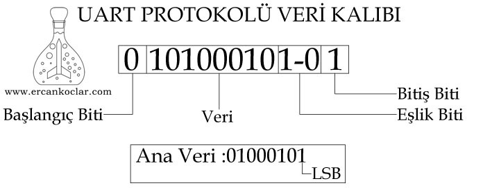
- The data pattern consists of 4 parts:
- Start bit – 1 bit start bit, starts the communication pulls the line from 1 to 0
- Data– 8 bits (can be variable, 8 bits in my library) host data is sent in series.
- Parity bit -The 1 bit parity bit is 0 or 1 depending on the situation, allowing the accuracy check to be done quickly where the data arrives
- End bit – 1 bit end bit pulls the line at 1, so it is understood that the communication is finished
A1 – Start Bit
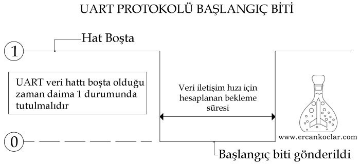
- Always 0 ( zero)
- The line should always be kept high, otherwise fluctuations can lead to erroneous communication start.
- The start bit is at the same time the synchronization bit therefore it always pulls the line from 1 to 0 and allows the communication to start at the same time
- When data is getting read, the line is expected to be pulled at zero and the reading starts once it is zero.
A2 – Main Data
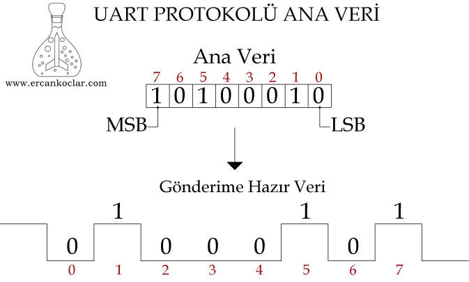
- Generally 8 bits are used.
- The data we want to transmit is changed from paralel to series.
- While transmitting data, always must start from the LSB.
- The data transmission package may be 7 or 9 bits in some libraries, check the help files for this. In my library, 8 bits are preferred for convenience.
- While reading the data, the first incoming data is also made meaningful by writing to the end, so the inverted data becomes old.
A3 – Parity Bit
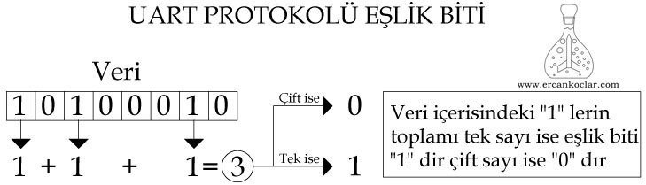
- Checks whether the data is transferred correctly.
- Generally, selected as 1 or 2 bit, I set 1 bit in my library.
- The parity bit calculation is as follows:
- If we take the Sample data, the binary state is “01000101“
- According to this, we sum “1” s which are in data, and there are 3 “1”s in total
- The parity bit will be “1” because the result is odd. If the result is even, the parity bit was supposed to be “0”.
- In fact, this can also be achieved by doing XOR between binary numbers themselves. The choice of method is up to you
- In the data reading, the 9th parity bit is stored and the parity bit is calculated for the incoming data. If the calculated bit and parity bits are the same, the data is transmitted correctly.
A4 – End Bit
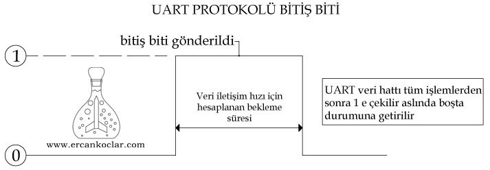
- Pulls the line to 1, indicating that the communication has been terminated.
- After the 9th bit, the line is pulled high (ie returns to idle state), which means that the communication is finished.
B- Calculate the Desired Speed and Time Required for Communication in the UART Protocol
- The data rate of the UART is measured in “bits per second” (bps)
- Example: If we want to communicate at 1700 bps speed
- 1/1700 = 5,88 we receive a value like this
- 5,88*100 = 588 us means micro second
- According to this, if we want to communicate at 1700 bps speed, 588 us ( micro second) wait should be done between every bit.
- Below is an example of a speed conversion calculation that may be needed
- Communication speed if considered as 25000 bps and find out how many kbps it is
- First of all, 25,000 bps can be thought of as 25 kbps with straight calculation, but this is wrong. Because the important thing is the data transfer, when we communicate with 25000 bps, we send the start-stop bits and the parity bit together with every 8 bits of data. This does not mean data transfer by itself. In that case:
- 1 start bit + 1 end bit + 1 parity bit + 8 data bit =11 bits in total
- We calculate 8 bits data transmission, 8/11 = 0,72
- 25 kbps * 0,72 = 18 kbps means that our real data transmission speed is not 25, but 18 kbps.The remaining time is the time spent for the start-stop-parity bit transfer.
- 18 kbps equals how many KB/s
- 1 byte = 8 bit
- 1 KB = 1.024 byte
- 1 KB = 1024*8 = 8192 bit
- 18.000 bps * (1KB/8192 bit) = 2,19 KB/s
- Means that if we set our speed at 18 kbps the data transmission equals 2,19 KB/second.
- Communication speed if considered as 25000 bps and find out how many kbps it is
UART Protocol Result
- Now that you have the theoretical knowledge about the UART communication protocol.
- How is data communication? How do they start? How should a data be taken as pattern? You can write your own functions as you know about them, or else you can check my MicroC library that I have prepared and use accordingly.
UART Protocol MicroC Library
- You can use the UART protocol independently of the PIC hardware with the library I write in MicroC.
- The study was tested with the 18 f series PIC.
- The functions fulfill the basic functions. You can set up the remaining complex tasks yourself with these functions
- No interrupt and timing is used in the functions, so you do not have to give up timing and interrupts for a library (as in the standard library of a MicroC)
Functions
- After basically seeing functions as parameters, I will explain with two detailed examples
- All of the functions are user functions. There is no need to use only the parity bit calculator. It is used within the function, but you can also use it only for the parity-end account in your own projects.
- User functions are functions written for the user, system functions are used in the system, so calling up the system functions can cause problems in operation.
–UART_VERI_TAMPONU General Series
- Since this is generic, it can be called from anywhere in the program and the array of the same name can not be created.
- Arrays were used for communication between functions. The elements of the array are as follows:
- uart_veri_tamponu[11]={0,0,0,0,0,0,0,0,0,0,1}
- 1st bit =”0″ For UART start “0” data must be sent.
- 2-9th bit = It’s the 8 bit that carries the data to be sent.
- 10th bit = It is the parity bit, it determines whether the data is going correctly
- 11th bit =“1” UART sends “1” data in the end.
- NOTE: You do not have to do any extra work to read the data. Reading function breaks the incoming raw data and returns the necessary data part. This explanation is for informational purposes only. If desired, any data in the series can be read.
– UART_ESLIK_BIT_HESAPLAMA Function
Function : unsigned char UART_ESLIK_BIT_HESAPLAMA(unsigned char VERI)
Purpose :
- Calculates parity bit required for 8 bits data.
- This function used with control purpose both when sending data and when receiving data.
Parameters :
- VERI : The 8 bits of data to calculate the parity bit are written
Type of Use:
UART_ESLIK_BIT_HESAPLAMA(VERI);//variable or data can be written directly
Feedback : Returns the required parity bit
– UART_GONDERILECEK_VERI_AYIKLAMA Function
Function: void UART_GONDERILECEK_VERI_AYIKLAMA(unsigned char VERI)
Purpose: uploads the splitting the main data to “uart_veri_tamponu” before sending it
Parameters:
- VERI: The data to be extracted is loaded here, consists of 8 bits.
Type of Use:
UART_GONDERILECEK_VERI_AYIKLAMA(VERI);
Feedback:
- Does not give feedback.
- It is a system function
– UART_VERI_GONDER Function
Function : void UART_VERI_GONDER(unsigned char VERI)
Purpose : 8 bits data is sent to receiver ( it calculates the parity bit itself and there is no need to calculate it)
Parameters :
- VERI : Carries 8 bits of data to be transmitted
Type of Use :
bilgi=0b00001111;

UART_VERI_GONDER(bilgi) ; // sends 8 bits of data assigned to the info variable
Feedback: Does not do feedback
–UART_AYIKLANMIS_VERIYI_BIRLESTIR Function
Function: unsigned char UART_AYIKLANMIS_VERIYI_BIRLESTIR(unsigned char *veri_hatasi)
Purpose: It takes the fragmented incoming data as a whole and retrieves it from the 8 bits carrying meaningful information.
Parameters:
- *veri_hatasi : The parity check is obtained by reading the value of this pointer. If pointer
- 1 means that there is a mistake
- 0 means that there is no mistake
- This does not return as a function value, the value of the pointer must be read directly
Type of Use:
unsigned char hata_kodu;

UART_AYIKLANMIS_VERIYI_BIRLESTIR(&hata_kodu);//the error code variable is assigned the value that the pointer receives
Feedback:
- The function returns a significant value of data
- It is unconditionally necessary to read the *data_error pointer to see if there is a data transfer error
- 1 means that there is a mistake
- 0 means that there is no mistake
- System function
– UART_VERI_AL Function
Function : unsigned char UART_VERI_AL(unsigned char *hata_kodu)
Purpose: Receives and checks the incoming 8-bit data from transmitter
Parameters :
- *hata_kodu : It is Pointer, if the data is transmitted incorrectly, this pointer reads 1
Type of Use:
veri=UART_VERI_AL(hata) ;//the incoming information is assigned to the data variable
Feedback :
- The function sends the read data to itself
- It is checked with *error_code pointer whether there is an error . If there is a mistake on data, it will be 1 this data should not be considered
– Determination of Communication Speed
- Since the communication speed is independent of the hardware, it is set in the UART.h file in the library
#define UART_ILETISIM_HIZI Delay_us(833);// (1/bps)*1000000 =xxxus
- In the above code, content of Delay_us(833) or entirely itself can be changed and the waiting period added here will determine the waiting time in the communication.
- The time calculation is shared next to the above lessons and codes.
- Accordingly (1/desired speed) *1000000 =will give us the necessary waiting time for this speed.
- The receiver and transmitter PICs must always communicate at the same rate.
Function Application
- Application part is considered as two subject as receiver and transmitter codes.
Transmitter Code Example
//UART PIN IDENTIFICATION
 sbit UART_RX at RC7_bit;
 sbit UART_TX at RC6_bit;
 sbit UART_RX_Direction at TRISC7_bit;
 sbit UART_TX_Direction at TRISC6_bit;*/

void  main()
{
    unsigned char veri;
    ADCON1=13;
    CMCON=7;

    veri=0b00001111;//8 bit our raw data

    UART_VERI_GONDER(veri) ; //datas are sent from transmitter Pin
}
- First, we identify pins we use the UART.
- Then the required data is sent with the function “UART_VERI_GONDER” either by writing the variable or the data directly.
- Also, there is no need to calculate the parity bit, the function performs its own calculation.
Receiver Code Example
//UART PIN IDENTIFICATION
 sbit UART_RX at RB2_bit;
 sbit UART_TX at RB3_bit;
 sbit UART_RX_Direction at TRISB2_bit;
 sbit UART_TX_Direction at TRISB3_bit;


void  main()
{
    unsigned char veri =0 ,hata=0;
    ADCON1=13;
    CMCON=7;

   //One LED is connected to the Pins and closed while starting
    trisb.rb1=0;
    portb.rb1=0;


 do{
     veri=UART_VERI_AL(&hata) ;//receiving data function-
   }while;
/*note:if it is desired to leave the above loop condition to the user, the 0 start bit can be waited in the wired communication,
 but at least 8 bit pre-authentication data must be used in the wireless communication,
so the data communication start cycle is set here.*/

if(hata==0)//if there is no error in the data transfer - if the pointer read is zero,
then there is no error.
  {
    if(veri==0b00001111)
      {
        portb.rb1=1;// if the data is received correctly, open the LED       }
  }
}
- Pin identification is done first
- In order to recognize that the requested data is coming, the LED is connected and the LED is turned on if the condition is correct
- Data is read with “UART_VERI_AL” function.
- The wait-for-read routine is set up with the “do-while” system. the condition to be used here is the user, is that, if it is a wired system, only the initial bit zero can be expected, but if it is a wireless system, a minimum 8 bit pre-authentication code may need to be used, so this condition is set in this section.
RESULT
- Now that you know about the operation of the UART protocol, you can write your own functions or you can also use my MicroC library
- UART is mainly used in RF transmitters, so I decided to write this protocol first for this purpose.
- PIC or other MCU hardware may have UART modules, but not every PIN, so this library can be used on the desired pin apart from the UART hardware.
- You can ask your questions on the forum.
Library Files
References
- afPro UART Protocol _ Afero
- Basics of UART Communication
- Electric Imp – UART Explained
- Electric Imp – UART
- Implementation of a digital UART by VHDL
- KeyStone Architecture
- MSP430 USCI Birimi ve UART Uygulamaları – Elektronik Devreler Projeler
- standardized-uart-protocol
- UART – Serial communication
- UART Details
- UART Protocol
- Uart Slip Protocol
- UART vs SPI vs I2C _ Difference between UART,SPI and I2C
- uart
- UART_001-13628_0J_V
- Uart_Serial Communication Basics Tutorial
- UART_v2_30 (1)
- UART_v2_30
- Universal Asynchronous ReceiverTransmitte
- Universal_Asynchronous_Receiver_Transmitter_UART_RS232
- USART and Asynchronous Communication
- USART vs UART_ Know the difference _ EDN


