This post is also available in:
![]() Türkçe (Turkish)
Türkçe (Turkish)
Hydraulic Press and Hydraulic Systems
Building the Hydraulic Press
Appendix – Calculating the Force Applied by the Hydraulic Press
Hydraulic Press Construction and Hydraulic Systems
In this article, I walk you through the step-by-step process of building a hydraulic press. This homemade press machine was designed as a 10-ton hydraulic jack project and features a robust structure suitable for metalworking tasks such as metal forming. Additionally, using a pressure-based calculation method, we accurately measure the power of the system. If you’re interested in building your own press machine at home, this guide is just what you need.
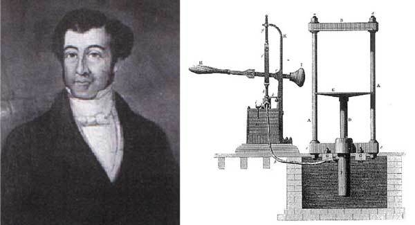
Hydraulic systems were first used by Joseph Bramah for shaping leather. Today, hydraulic systems are utilized in a wide range of fields—not just in press applications, but also in industrial machinery and heavy equipment.
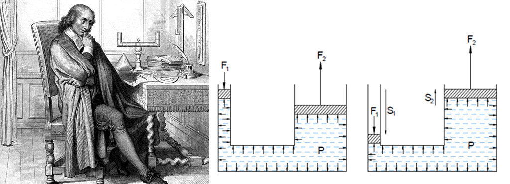
Hydraulic systems operate based on Pascal’s principle. The pressure applied to a fluid in a closed container is transmitted equally in all directions. This principle allows a small force to be distributed over a larger surface area, generating enough power to lift heavy objects.
Homemade Hydraulic Press Construction Steps



ALWAYS FOLLOW THE SAFETY WARNINGS ABOVE AND USE PROPER PROTECTIVE EQUIPMENT
1) Hydraulic Press Unit Installation
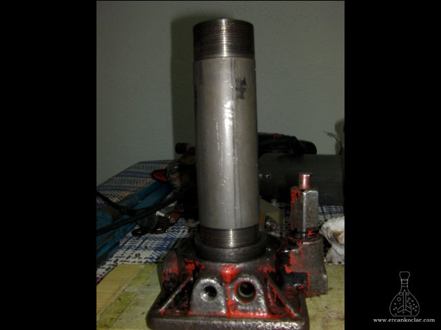
The most practical and cost-effective method for building a hydraulic press is by using a hydraulic jack. This project was essentially developed as a 10-ton hydraulic jack system. I chose a car jack with a 10-ton capacity. Although it is rated for 10 tons, achieving this pressure manually requires significant force. In this section, you’ll find the step-by-step installation process of the hydraulic unit for the homemade press machine.
Hydraulic units of this type typically do not include a pressure gauge. However, since this system was developed not only for lifting vehicles but also for scientific and technical testing purposes, a pressure calculation method is essential. Therefore, a 100 BAR glycerin-filled pressure gauge was added to the system. Warning: Dry (non-glycerin) gauges should not be used.
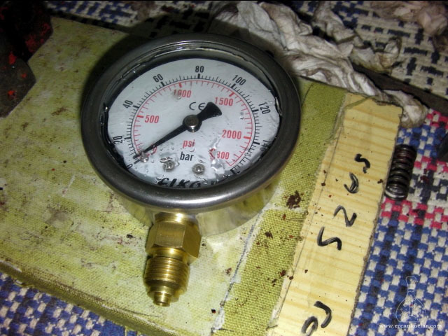
During system installation, the oil must be completely drained, and internal hydraulic components should be cleaned with thinner if necessary. (Thinner should not be used before removing the O-ring parts.) A hole with a diameter of 3–4 mm is drilled into the body, and a channel connected to the gauge is integrated into the system. This channel transmits pressure to the gauge.
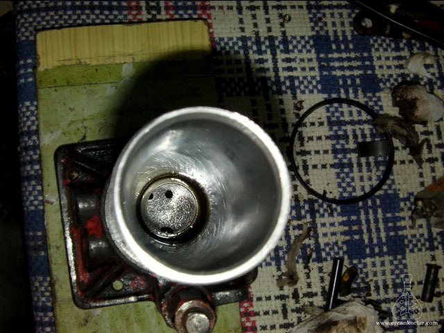
For the connection, fittings with steel bushings specifically designed for hydraulic systems must be used. Additionally, when the hydraulic unit is disassembled, the pressure seals on the main shaft should be checked and replaced if necessary. At this stage, the selected seals must be rated for the expected system load.
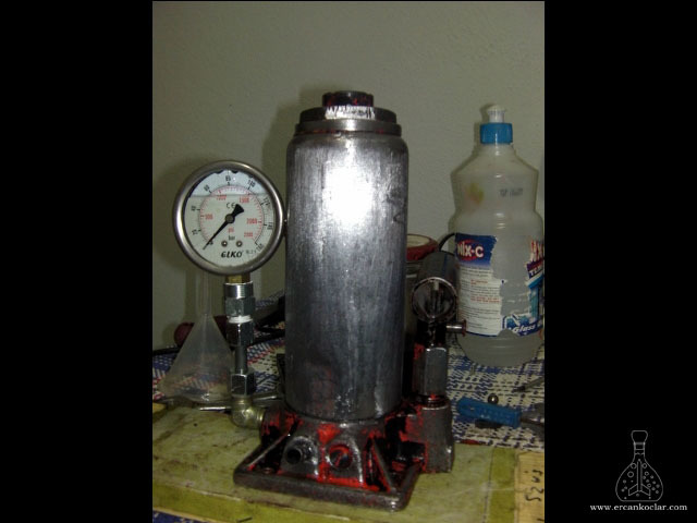
The system is now capable of generating pressure. In the image, the component on the left is the piston responsible for pressure relief, while the one on the right is the safety outlet that activates in case of high pressure. This section must not be modified and should be kept in its original form—otherwise, safety risks may arise during hydraulic press operation. The pump on the right-hand side corresponds to the F1 piston and generates pressure by pushing oil through the system. A check valve (one-way valve) is located in this section.
2) SPACERS / BLOCKS
This homemade press machine was designed to compress clay and fuel used in model rocket engines. One of the technical challenges encountered during construction was the lack of an upper pressing plate, since the system was based on a hydraulic jack. The jack shaft was relatively thin, making direct mold usage impractical. To overcome this, circular metal blocks with a thickness of 30–40 mm were sourced from scrap yards and repurposed into solid press plates suitable for metalworking.
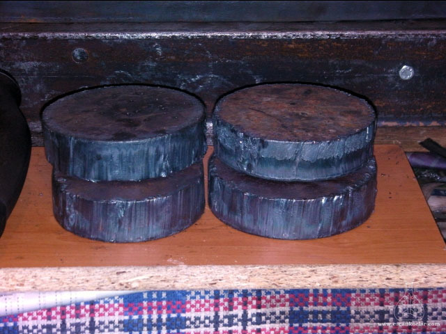
The Optimum D210x400 benchtop lathe can handle parts up to a maximum diameter of 100 mm. However, since the required spacer diameters were larger, a new solution was developed. Metal rods were attached to the spacers and then mounted onto the lathe chuck to ensure balance. This technique made it possible to work on larger diameter metal parts.
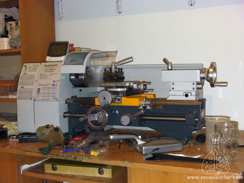
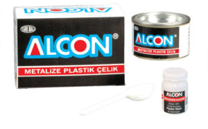
A strong adhesive called “ALCON – metallized steel” was used to bond the rods to the spacers. This product, which includes a black adhesive and an orange catalyst, provides high durability in metal applications. After application, a 24-hour curing period ensured complete bonding. With this method, the spacers could be mounted on the lathe and machined symmetrically.
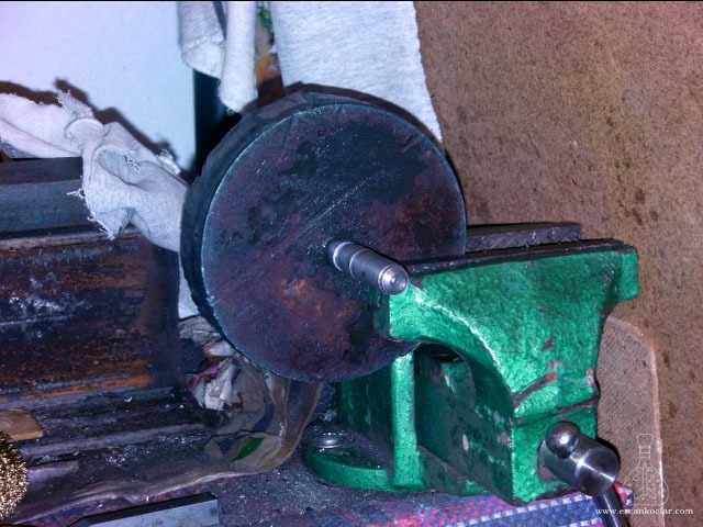
First, I located the center of each spacer and drilled a hole with a 10 mm drill bit. Then I inserted a rod of matching diameter into the hole and bonded it with metal adhesive. To ensure a strong bond, I allowed it to cure for 24 hours. During this phase, it’s crucial that the spacer does not move—securing it in a vise is the safest solution.
After the curing process was complete, I mounted the spacers onto the lathe and began machining. These parts, prepared for the homemade press machine, had uneven and unbalanced surfaces, so they required careful machining. Since they do not rotate perfectly centered at first, some wobbling may occur; however, this irregularity decreases as the lathe progresses.
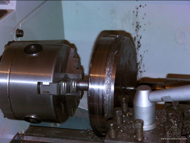
The machining process must be slow and controlled. Working too fast can break the diamond-tipped cutting tools used in metalworking. Special care should also be taken against the formation of burrs. Remember: Burrs should never be removed by hand—whether the machine is running or stopped—as they can cause serious cuts.
Both the front and rear surfaces of the spacer must be machined using the correct cutting tools and angles. An uneven surface can cause the mold to shift during pressing, leading to misalignment and pressure errors. These steps are essential for creating a strong and reliable pressing platform in the construction of a hydraulic press.
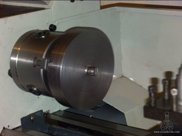
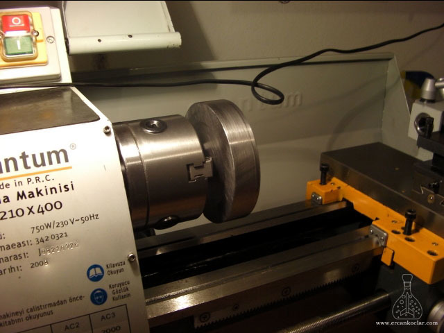
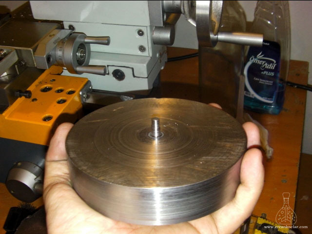
After nearly a full day of turning and surface correction, the spacers required for the hydraulic press construction reached the desired shape. The surfaces, now smooth and polished, were completely transformed and made suitable for use as press plates. The central rod can be removed if necessary; I kept it fixed to help with mold alignment.
The reason I used multiple spacers was because this homemade press machine was intended to compress short rocket motors. However, since the system was designed based on the largest motor size, there would have been too much space between the press plate and the top point. When the diameter is small and the length is large, the rod can easily bend or deform under pressure. To reduce this risk, I stacked multiple spacers to optimize the height. This configuration offers a robust solution for projects such as metalworking and rocket motor compression.
3) CONSTRUCTING THE FRAME
The most critical part of a hydraulic jack project is a solid and rigid frame. The frame must have a strong skeletal structure capable of withstanding high pressures. Since this structure will operate under constant stress, weak materials or poor welding can cause it to fall apart in just a couple of days. Therefore, using sturdy steel profiles and proper welding techniques is essential during frame construction.
To reduce costs, I sourced the parts from scrap yards. In the market, steel profiles are usually sold in 6-meter lengths, which poses both economic and transportation challenges. That’s why working with recycled materials turned out to be a very practical decision.
The AutoCAD plan is provided as an attachment. The frame design primarily uses NPU100 and NPU50 U-profiles, as well as 50×25 mm flat bars and M18 threaded rods. This combination provides the required pressure resistance and structural stability for the project.
3A) RUST AND RESIDUE REMOVAL
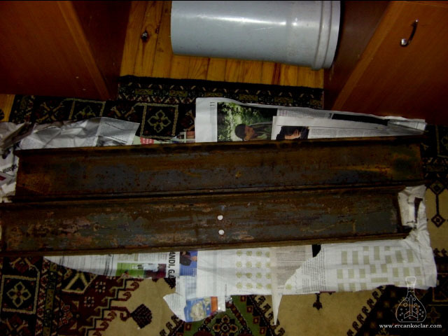
To ensure the hydraulic press is durable and long-lasting, the frame components must be cleaned of rust and debris before welding. This was done using steel wire brushes attached to a drill—a commonly used, practical method in metalworking. It provided fast and effective results and prepared the surface for painting.
WARNING: Wire brushes may throw off bristles while spinning. Always wear protective gear such as safety glasses and gloves.
3B) FRAME CUTTING PROCESS
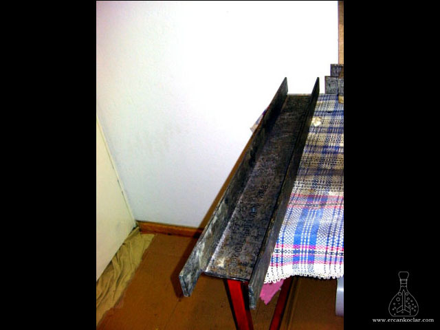
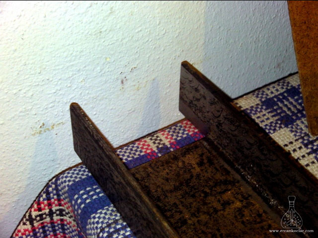
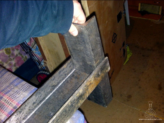
In the homemade hydraulic press, NPU100 profiles serve as the main support columns, while NPU50 profiles are used as crossbeams. For this reason, the ends of the NPU100 profiles must be carefully cut and filed to create smooth, even surfaces.
3C) DRILLING HOLES FOR SUPPORT RODS
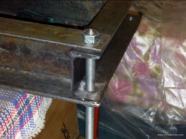
To increase the structural strength of the frame, M18 threaded rods were incorporated into the design, requiring 18 mm diameter holes. Since I didn’t have a drill press available, I successfully completed the drilling process by mounting the appropriate drill bit in the lathe chuck as part of the homemade press project.
3D) WELD PREPARATION AND APPLICATION
To enhance the durability of the press frame, weld beveling was performed. Since the frame consists of thick steel profiles, the bevels must be sufficiently deep to ensure strong electrode weld penetration.
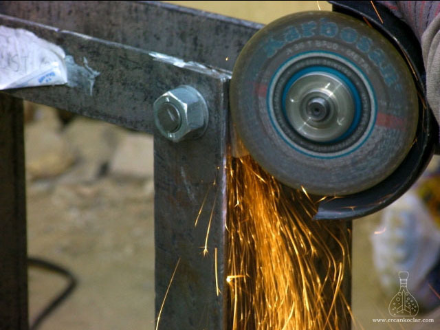
WARNING: When attaching the grinding disc, always pay attention to the direction of rotation. The labeled side of the disc must always face inward toward the tool. This detail is critical for both safety and operational quality.
Following these steps ensures a strong and durable frame structure for the homemade hydraulic press project.
3E) WELDING PROCESS AND SAFETY PRECAUTIONS
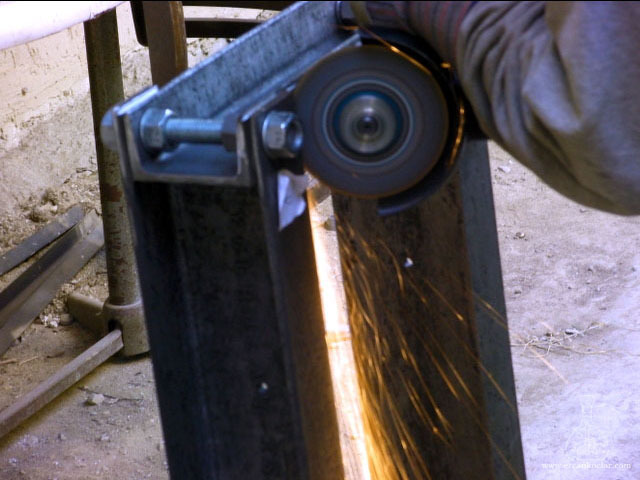
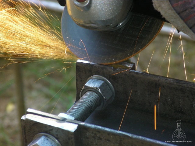
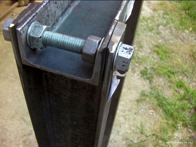
Before welding, all joint areas must be beveled. In this project, 2 mm welding electrodes were used, so the bevels were opened in a conical shape with a minimum width of 2–4 mm. This allows the weld metal to penetrate deeply and results in a structure capable of withstanding high pressure.
SAFETY WARNING: Welding involves potentially fatal risks. If you have no prior experience, seek assistance from a qualified professional. Do not extend the grounding cable (chassis) using additional connectors; instead, use a single continuous cable. Otherwise, high resistance may cause the current to pass through your body, which can be fatal.
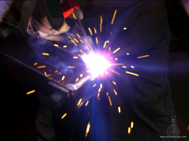
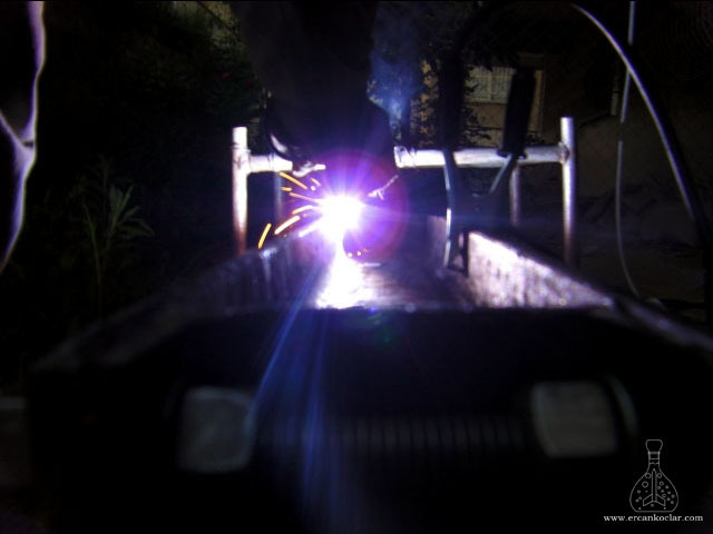
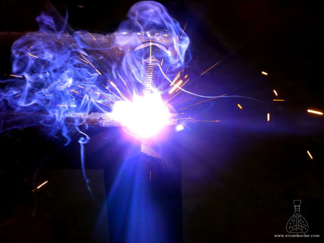
Welding gloves, a welding mask, and safety goggles are absolutely essential. In electrode welding, slag should be removed before applying the next pass—do not weld over it. I used a current of 100–120 Amps for this process, but you should adjust according to the material thickness.
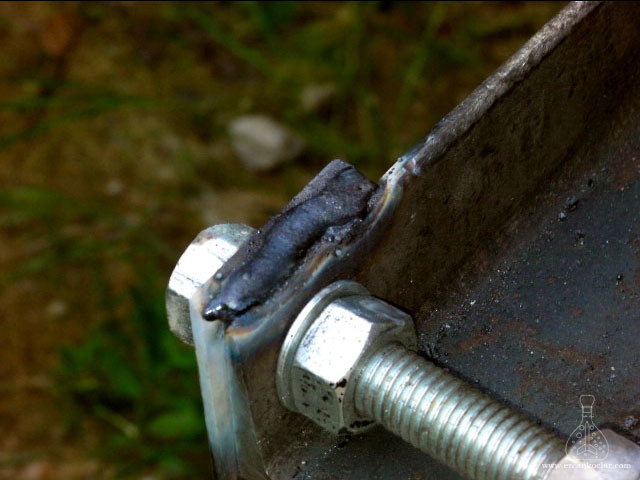
After welding, remaining slag must be removed once it has cooled. If there are any gaps or underfilled areas in the weld, they should be filled. This step enhances both the durability and the visual quality of the homemade hydraulic press project.
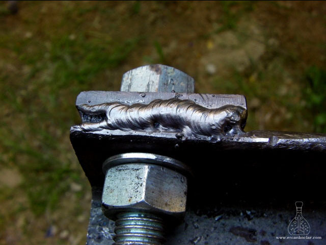
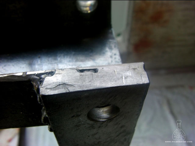
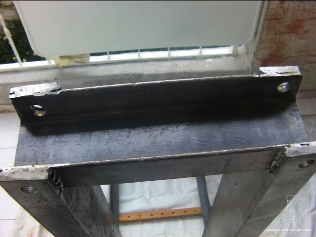
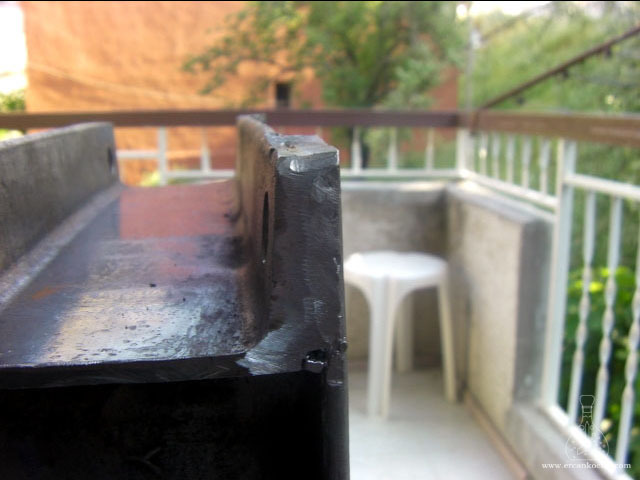
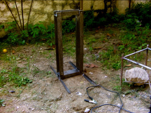
The hydraulic press frame is now complete. To keep it upright, 40×40 mm L-shaped angle irons were welded to the base. The threaded rods will now be removed, and the system will be tested using the hydraulic unit. This process is shown in the video at the bottom of the page. It also serves to evaluate the quality of the welding.
4) PAINTING PROCESS
After successfully passing all tests, the press was painted with 2 to 3 coats of gray anti-rust primer. Then, two more coats of high-quality red paint were applied. Before painting, cracks and rough surfaces were filled and leveled using polyester body filler.
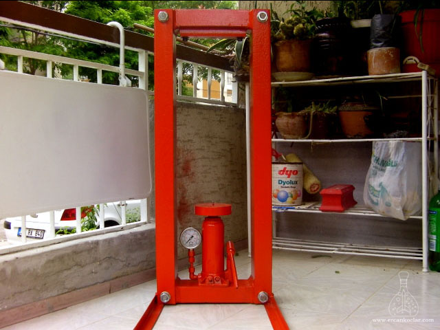
In the final step, a thick flat bar was secured to the upper NPU50 profile using steel screws. This area is prone to deformation due to pressure, so using screws allows for future replacement if necessary.
For more details, you can watch the video below.
“HYDRAULIC PRESS CONSTRUCTION” VIDEO
APPENDIX – HOW MUCH FORCE DOES THE HYDRAULIC PRESS APPLY?
The installed gauges only display pressure. Therefore, we need to perform some measurements and calculations to determine the applied force. First, we need the surface area of the cylinder bore—specifically the internal diameter—which tells us the area being pressurized by the hydraulic fluid.
- Measure the Internal Diameter of the Cylinder
- Using the internal diameter, calculate the surface area (formula: π·r²), which represents the area on which hydraulic pressure is applied when the system operates.
- Constants:
1 bar applies 0.1 newton per mm² - Constants:
1 kg = 9.81 newtons (gravitational acceleration)
Surface Area Calculation:
- Surface area = 3.14 cm × 3.24 cm = 10.17 cm² = 1017 mm²
- Force at 1 bar:
1017 mm² × 0.1 N/mm² = 101.7 newtons - Converting to kilograms:
101.7 N ÷ 9.81 = 10.3 kg
- Result:
A press with a surface area of 1017 mm² applies approximately 10.3 kg of force at 1 bar.
📐 Technical Plan for the 10-Ton Hydraulic Press
- Hydraulic Press Design (Password: www.ercankoclar.com)
- Hydraulic Press Inventor Files (Password: www.ercankoclar.com)
📄 Technical Documents
- Design and manufacturing of a hydraulic press used in composite material production
- Hydraulic and Pneumatic Circuit Component Drawings
- Hydraulic Systems
- Use of Statistical Methods in Hydraulic Studies
- Hydraulic
📌 Project Summary and SEO Information
Focus Keyword: hydraulic press build
Meta Description:A 10-ton homemade hydraulic press project. This page includes the full technical drawing, force calculations, and a step-by-step construction guide.
Tags:#hydraulicpressbuild #homemadepressmachine #10tonjackproject #metalworkingprojects #forcecalculationmethod
🔗 For more on how hydraulic presses work, check the Wikipedia page on hydraulic systems.
This post is also available in:
![]() Türkçe (Turkish)
Türkçe (Turkish)
Comments are closed.