This post is also available in:
![]() Türkçe (Turkish)
Türkçe (Turkish)
- What is I2C ?
- Objective of the Protocol I2C
- Creating the Required Structure for I2C Protocol
- How Does the I2C Protocol Work?
- I2C Protocol Result
- I2C MikroC Library
- I2C Functions
- Application of Functions
- Result
- Library Files
- Documents Taken
- I switched to the I2C protocol for a project I needed to use RTC (DS1307). However, the PIC te built-in I2C module pins were full. For this reason, I prepared an I2C protocol and a library that can operate on any desired PID.
- With this library it can be communicated by using any 2 pins of PIC.
- After telling about the I2C topic, the use of the library will be explained.
1- What is I2C ?
- I2C is a software protocol that allows communication over 2 pins.
It was created by Philips (NXP).
An integrated or component can be used with this protocol if the I2C system is present. This means that if there is no I2C in RAM, it can not be used with this protocol.
In the I2C protocol, the manager MCU is called “master” and the other part is called “slave”.
| Positive sides | Negative Sides |
| It is flexible. You can develop as many slaves and master / slave parts as you like within the system. | Address conflicts can occur because part addresses are defined when they are generated. |
| It makes selection based on address. So you do not need an extra CS (chip select) pin. | Speeds are limited compared to other parallel communication systems. |
| The connection is simple. Even if you use more than one part, only 2 lines are connected | In some cases, putting too many pull-up resistors can lead to stress on the PCB’s surface area. |
| There are error detection systems, ACK and NACK. This tells you whether the process is correct or not. (to be described later) | |
| It works with all parts with this protocol regardless of speed. |
2- Objective of the Protocol I2C
- The I2C protocol aims to drive only the parts that normally require too much pin separation using only 2 pins.
In the I2C protocol, only 2 pins can be separated and many RAM, EEPROM, RTC etc. parts can be connected and used on the same line. This also removes the need for extra pins.
Other MCUs can be connected to the line in the I2C protocol. They can take place as both master and slave at the required times.
3- Creating the Required Structure for I2C Protocol
- Basically, there is no need for an extra circuit. Only SDA and SCL ends are pulled up with resistors.
- The I2C protocol has 4 speed ranges.
- 100 kbit / s
- 400 kbit / s
- 1 mbit / s
- It can operate at 3.2 Mbit / s speeds. However, the parts used must support these speeds.
- Although there is a calculation method for the resistors to be used, I will now give the standardized values here. Because the correct calculations can be made to connect to the I2C protocol to calculate the resistance of the copper roads to pieces is required.
- The following table can be used to select pull-up resistor values for the speed to be used.
Mod Speed Resistance Range Standard Mod 100 Khz 5kΩ – 10kΩ Fast Mod 400 Khz 2kΩ – 5kΩ High Speed Mod 3,4 Mhz 1kΩ - The line to be used for the I2C protocol should not be too long. This communication protocol is suitable for short distance.

4- How Does the I2C Protocol Work?
- The I2C protocol basically consists of 4 steps. These:
- START – Contact start sign
- ADDRESS – Indication of the address of the part to be contacted and read / write
- DATA – Initiate the data traffic to be read
- STOP – Stop communication
- The acknowledgment (ACK / NACK) code after the transaction
- The “1” pin is pulled high and the “0” pin is pulled down.
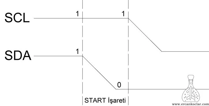
4A- I2C “START” Contact Start Mark
- Before the commencement of the communication, the START signal is sent and all connected parts are switched to the stand-by position.
- For the START sign,
- When SCL = 1 SDA=1
- SCL = 1 SDA=0 so that the signal is sent.
- The point to be noted is; After START, SDA=1 will be made to continue the communication. However, SCL = 0 should be made before SDA=1. Otherwise, if SDA=1 while SCL=1, it leads to the fault.

4B- I2C Address and Transaction Mark
- The addresses of the parts are 7. The data indicating the operation to be performed is 1 bit. That is, 8 bits (1 byte) will be sent in total.
- According to this,
- The 8th bit should be “0” if the write operation is to be performed.
- If reading is to be done, bit 8 should be “1“.
- For example, if the address is 1001001 and write is made, the block to be sent must be 10010010.
- After the address is sent, ACK, which is the confirmation code from the part, comes. I will explain this in detail in Article 4E.

4C – I2C “DATA” Data transfer
- The data are sent as 8 bits.
- The SDA and SCL locations are as follows when sending data.
- SCL=0 must be made before loading the SDA pin data.
- SCL=0 SDA=1 or 0 (SDA is set according to the bits to be sent)
- When SCL=1, the uploaded data on SDA is sent.
- After each data is sent (8 bits sent), the acknowledgment code ACK comes from the piece in the dialog. I will explain this in detail in Article 4E.
- SDA and SCL locations are as follows when reading data.
- As opposed to writing in the data read, SCL=0 and SCL=1 are made.
- In this case, the data on the SDA pin is read.
- Whenever we read the data (when 8 bits are read), we will send a confirmation code ACK to the part if we continue to read it. If the reading is to end, then we send the NACK code so that the reading of the piece ends.

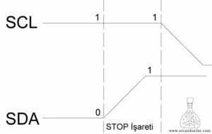
4D- I2C “STOP” Communication Stop Sign
- The STOP stop signal ends all communication.
- For STOP sign
- SCL=1 SDA=0
- When SCL=1 SDA=1, all communication is terminated.
- Again, SDA and SCL are always in position 1 because the point we need to be careful is pull-up. To make SDA=1 in SDA=0 we must first get SDA=0. For this reason, the SDA pin must always be set to SCL=0 before SDA is set.

4E- I2C Check Mark (ACK – NACK)
- When we send the address or data to the part we will send the confirmation code to us. This acknowledgment code is ACK (acknowledge).
- When this acknowledgment is received, the SDA pin normally goes to “0” state when it is “1” due to pull-up. Thus, the ACK confirmation code has arrived.
- As we read the data in the opposite way, we will send the ACK to the part and continue reading. When the last reading is finished, we leave the 9th bit as 1 instead of 0. This causes a NACK to be sent and the communication to be stopped.
- For this reason, the 9th bit is always checked when an address is sent or data is written. If the confirmation code does not appear, the entire transaction must be canceled and communication must be restarted by sending the START signal again.
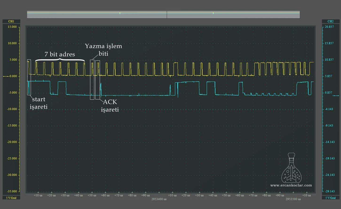
- Let’s examine a complete data communication from the chart below.

- As you can see above, the 7 bit address after the START and the 8th bit telling you to write together are sent.
- After that, the clock continues to be sent with SCL. After the 7 bit address and 1 bit operation signal, the part we are communicating with the clock sends ACK by pulling the SDA pin zero.If confirmation is not received, communication should be renewed. After this, all the data to be sent will be sent with the addressed part first.
- The address was confirmed by the track and we stated that we would write. Now we are sending 8 bits of data and we are waiting for the 9th bit check code. The part again pulls the SDA pin and confirms that it is successful in writing the data.
- NOTE: If we do not read while writing, we create the ACK code. So after reading the 8 bit data, we get the SDA pin zero. Thus, the reading process continues. When reading is finished, we send NACK this time after the last 8 bits read. So we leave SDA at 1 and send only clock. This means that the track reading process is finished.
- Then the communication with “STOP” sign is terminated. If desired, data can be written continuously without stopping.
- There is no restriction in this.
If you want to read more than once while writing, we follow the same path with the START mark. - Below you can see a real communication on the oscilloscope.

I2C Protocol Result
- You have information about the I2C protocol. The above operation describes a general communication.
- Each part has its own communication system. That is, when writing data to an I2C RAM, the address of the write destination area is sent except for its own address. Some parts are written directly. Inside the pointer, each data is spontaneously incremented. That is, the basic system may be the same, but the operations may be different. You should learn these by looking at the parts data sheet.
- As a newly added feature some parts now have 10 bit adrese. It also has a method of sending. But I did not want to add it to my heart because I do not use it right now. I will make the necessary updates when it comes to my future projects. However, this basic system is also valid. This can be done with the existing system and library functions. No extra joints were needed.
- Now that you know the protocol, we can switch to the I2C Library, which I wrote in MicroC.
I2C MikroC Library
- This library is written in accordance with PIC18. Conversions can be made in PIC16 if needed.
- The purpose of the library is to perform I2C operations with the desired 2 digital pins, regardless of the PIC’s I2C module.
- In general, I2C libraries can have START and RESTART functions. In this library, the START-START function is used in both processes.
- The communication speed is determined by the function in the software using the PIC module. This purpose calculates the required waiting time within the PIC module. However, since we are independent of the module here, the necessary speed setting is set in the .h header file supplied with the library file.
- To make a speed ;
- 1 khz = 1000 us
- 100 khz = 10 us
- 400 khz = 2,5 us must be.
- Now you can see the functions
1- I2C Functions
- The functions are the basic functions that meet all I2C communication needs. Using them you can communicate with all I2C parts.
– I2C_ILETISIM_BASLAT Function
Function : void I2C_ILETISIM_BASLAT()
Purpose : Initiates I2C communication. It is also used in place of restart.
Parameter : No
Usage :
I2C_ILETISIM_BASLAT();// starts I2C communication
Feedback : It does not return any value since it is a void type.
– I2C_ILETISIM_DURDUR Function
Function : void I2C_ILETISIM_DURDUR()
Purpose : ends communication
Parameter : no
Usage :
void I2C_ILETISIM_DURDUR()//Ends communication in any case
Feedback : It does not return any value since it is a void type.
– I2C_VERI_YAZ Function
Function : unsigned char I2C_VERI_YAZ(unsigned char veri)
Purpose : It sends 8 bits of data to the connected part.
Parameter :
- veri : The 8-bit data to be transmitted is loaded into this parameter.
Usage :
I2C_VERI_YAZ(0b01010101)//The register addresses of the slave device in data writing and communication are sent with this function.
Feedback :
- If it returns 1 value, the operation is successful.
If it returns 0, the operation is not successful.
– I2C_VERI_OKU Function
Function : unsigned char I2C_VERI_OKU(unsigned char sonlandir)
Purpose : It reads 8 bits of data from the connected part.
Parameter :
- sonlandır: If reading is in progress, “end = 0” (ACK) is done if reading is in progress so the track knows that reading will continue. However, if the reading is to be terminated, the reading operation is terminated by performing “NACK” when the last reading is performed.
Usage:
I2C_VERI_OKU(1);// Once reading is done and reading is terminated
Feedback:
- Returns the read 8 bit value.
– I2C_ADRES_GONDER Function
Function : unsigned char I2C_ADRES_GONDER(unsigned char adres, unsigned char islem)
Purpose : It provides the address of the part to be contacted and provides the connection. It also determines whether the operation to be performed is writing or reading.
Parameter:
- adres : The 7 bit address of the part to be connected is written. This address writes the data sheet of the part.
- islem : Specifies the action to be performed.
- If process=0, it means writing will be done.
- If the operation=1, then the reading is done.
Usage:
I2C_ADRES_GONDER(0b01101000,0);// A 7-bit address was sent and write was specified.
I2C_ADRES_GONDER(0b01101000,1);// A 7-bit address was sent and write was specified.
Feedback :
- If it returns 1 value, the operation is successful.
- If it returns 0 the operation is not successful.
2- Application of Functions
- Below you will see an example of simple communication with the DS1307 clock integration. However, again, each piece is different in communication and order. For this reason, you should learn this rule from the data sheet of the relevant part.
- I will also write and publish a library for each track I use with I2C.
2A- Making Pin Identification
- If you use any of the pins for I2C, we specify them in this section.
//I2C Pin Tanımlaması
 sbit I2C_SDA at RA5_bit;
 sbit I2C_SCL at RE0_bit;

 sbit I2C_SDA_VERI at LATA5_bit;//27.01.2019 güncellemesi ile eklendi

 sbit I2C_SDA_Direction at TRISA5_bit;
 sbit I2C_SCL_Direction at TRISE0_bit;
2B- Determination of communication speed
- We set the link speed by increasing or decreasing the wait time from the corresponding location in the .h header file.
- Generally speaking, a value of 10 is suitable for 100kHz communication.
#define I2C_ILETISIM_HIZI Delay_us(10);// communication speed adjustment
2C- I2C Case Study
- It’s a very simple operation for the DS1307 integration. At least it may be useful to give an idea.
void  main()
{
    unsigned char veri[8];//the array created for writing the read data
    unsigned char txt[5];//created for printing the readout value on the GLCD and conversion operations.
    unsigned i =0;//Approval check was added to the condition.
    ADCON1=13;//PIC in A/D port setting
    CMCON=7;//the comparators were turned off.


    SAP1024_INIT (240,128,6);// added to see the results on GLCD.


    I2C_ILETISIM_BASLAT();//commnunication started
    do{i=I2C_ADRES_GONDER(0b01101000,0);}while(i==0);//The address is sent and it is checked whether the confirmation has come.
    I2C_VERI_YAZ(0b00000000);//register seçiliyor//ds1307 register is chosen
    I2C_VERI_YAZ(0b10000000);//writing is done
    I2C_VERI_YAZ(0b00000000);//writing is done
    I2C_VERI_YAZ(0b00000000);//writing is done
    I2C_VERI_YAZ(0b00000000);//writing is done
    I2C_VERI_YAZ(0b00000000);//writing is done
    I2C_VERI_YAZ(0b00000000);//writing is done
    I2C_VERI_YAZ(0b00000000);//writing is done
    I2C_ILETISIM_DURDUR();//communication is stopped

    //communication is restarted and ds1307 is activated.
    I2C_ILETISIM_BASLAT();
    I2C_ADRES_GONDER(0b01101000,0);
    I2C_VERI_YAZ(0b00000000);//register is being chosen
    I2C_VERI_YAZ(0b00000000);
    I2C_ILETISIM_DURDUR();


  // In this section, the continuous seconds data from DS1307 is read raw and printed on GLCD.
  while(1)

  {
    I2C_ILETISIM_BASLAT();
    I2C_ADRES_GONDER(0b01101000,0);
    I2C_VERI_YAZ(0b00000000);//register is being chosen
    I2C_ILETISIM_DURDUR();

    I2C_ILETISIM_BASLAT();
    I2C_ADRES_GONDER(0b01101000,1);
    veri[0]=I2C_VERI_OKU(1);
    I2C_ILETISIM_DURDUR();

    ShortToStr(veri[0],txt);
    SAP1024_YAZI_YAZMA(1,1,txt);
    delay_ms(1000);
  }

}
Result
- We came to the end of the lesson. With the I2C library you can also create libraries for parts you will use. So you can do things without making it easier and more complicated.
- You can ask your questions on “Forum“.
Library Files
Documents Taken
- I2C-bus specification and user manual-Ana Kaynak
- (SIO)
- AT03155 Real-Time-Clock Calibration and Compensation
- Eğitim Amaçlı Mikrobilgisayar Sistemleri İçin I2C Seri Haberleşme Protokolü ile Analog Arayüz Tasarımı
- I2C ECE353 Introducton to Mcroprocessor Systems
- I2C _ Android Things
- I2C Noise Glitch Filtering
- I2C Pull Up Resstors – Rhengold HeavyRhengold Heavy
- I2C Tutorial
- I2C_Bus_specification
- I2CBusTechnicalOverview
- Kontrol Sistemlerinde Kullanılan Veri Haberleşmesi Teknolojileri
- MİKROİŞLEMCİ SİSTEMLER
- Serial Communication
- Serial Interfaces SPI, I2C, UART Demystified
- The Essential I2C Tutorial_ All you need to know about I2C.
- Understanding the I2C Bus
- USB & RS232 TO I2CSPI ADAPTOR & CONTROLLER
- USB-I2C HW145-471959
- USB-to-I2C_Hardware_User_Manual
- Using the I2C Bus with HCS12 Microcontrollers
- Using the I2C Interface on the ATmega328P and MC908JL16
- Using the PICmicro® SSP for Slave I2CTM Communication
This post is also available in:
![]() Türkçe (Turkish)
Türkçe (Turkish)
